In the previous issue of “Elektronika”, the general capabilities of the robotic station for soldering built by Renex of Włocławek in cooperation with the Poznań University of Technology were discussed. The station uses a modern SCARA type robot. This article discusses the construction of the electronic controller of the soldering head and the whole station. Selected capabilities of its programming and operation are presented. The whole station is controlled by a PLC with an operator panel, which significantly improves its programming, setting up and operating. This makes it easy to control individual modules of the station, and the prepared and pre-tested soldering program can be reviewed and improved on an ongoing basis.
SOLDERING HEAD
A typical induction soldering head is used in the completed station. A special gripper was created to fix it on the robot’s working head and several variants of fixing the complete soldering head were designed and made. The holder for mounting the soldering iron is equipped with a guide rail, allowing to set the angle of inclination of the soldering head. This angle is selected for all soldering points on the board.
The soldering iron is attached to the sledge, moving on the guide rail. Inside the guide, a spring is placed, connecting the sledge with the guide. The mechanism with the spring allows to take a slightly lower overall position of the soldering tip and compensate for any local height differences by automatically moving the head along the guides.
This prevents the system from placing unnecessary strain on the head and tip at the bulging or bending point of the plate. In addition, as a part of the project has been developed and manufactured its own soldering wire guide to safely insert it into the soldering zone.
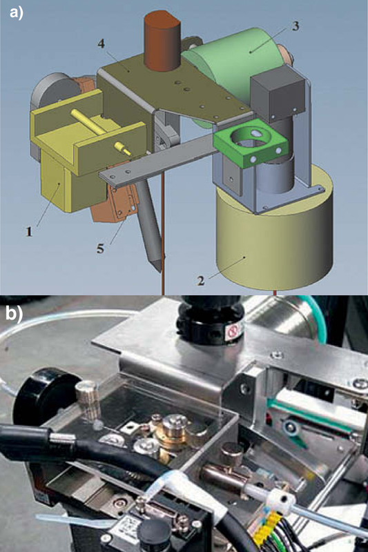
The articulated mounting allows the feeder needle to be adjusted so that the position of the needle allows the alloy to be brought to each soldered point without collision. The needle is an interchangeable element with an internal diameter that matches the soldering wire used by the station. The station uses a spherical joint at the point of attachment of the guide needle. Figure 1a shows the construction of the soldering head and its attachment. Figure 1b shows a picture of the head with a camera for quality control of the soldering process attached to it.
As part of the work, an in-house electronic control system for the soldering head was developed, manufactured and introduced to the market. It implemented functionalities allowing for its control by an external industrial controller working in a typical automation standard, which allows for diagnostics at the start-up and configuration stage. The soldering head’s active output power is controlled by master devices, i.e. the station’s electronic controller, via a 4÷20 mA current loop. The power supplied to the soldering head by the controller is set and is within the range of 4÷150 W.
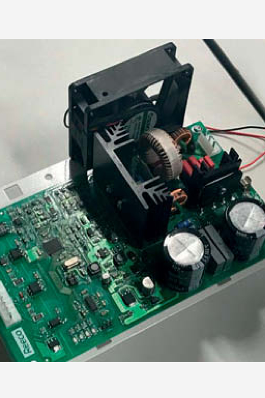
The main element of the control system is the Atmel XMEGA128A4U microcontroller, in which various control algorithms are implemented. Depending on the load, the system dissipates up to 20 W of power in the form of heat. Estimated controller efficiency is about 89%. In order to ensure its correct operation in conditions of long-term load and increased ambient temperature, forced air circulation cooling was used. Figure 2 shows the soldering iron controller. A linear heat sensor is placed in the soldering iron tip to provide information about the tip temperature. The soldering iron control module is equipped with self-diagnostics functions, whose task is to detect basic errors related to operation and to protect the system against their undesirable effects.
ROBOT CONTROLLER
The control system for the robotic soldering station consists of a PLC, a Human Machine Interface (HMI), a robot controller, a soldering iron controller, and other auxiliary equipment such as controllers of transport motor, soldering feeder motor and tip cleaning device motor.
There is also a nitrogen feeding system with a proportional pressure valve and flow meter, as well as a safety system to protect the robot’s working area and automation systems. The whole is complemented by several non-contact optical sensors, used to control the elements of transport and solder feeding system, mains temperature sensor and signaling column. A PLC type S7-1215 (Siemens) PLC in DC/DC/DC version was used, together with RS232 – CM1241 communication module, SM1223 additional digital I/O module.
In the front socket of the controller there is an SB1231 module with temperature input for thermocouple connection. The PLC is equipped with analogue inputs and outputs, 2 PTO type outputs for stepper motor controllers, and an Ethernet interface for communication with the HMI panel, as well as an RS232 interface for communication with the robot. The PLC controls the operation of 2 control systems, tip temperature and nitrogen feeding system. In both cases PID controllers are implemented in the PLC control program. The settings of both regulators were chosen experimentally, by trial and error method. The signal of soldering iron tip temperature is given to the front panel input of the controller.
The power value is determined by the PID controller and is sent to the soldering iron controller via an analogue output. The soldering station uses Siemens HMI 12-inch HMI panel type KTP1200 Basic. The large screen allows for easy programming and operation of the machine. To develop the controller and station panel software, a consistent TIA Portal programming environment was used. The advantage of this solution is also the high level of safety of communication between the panel and the PLC. Several different topic displays have been developed to operate the station, which visualize the current operating mode settings and elements allowing the user to make changes.
The developed display control software used mechanisms of sharing graphic elements from the template window, which allowed to create a graphically coherent layout of the control windows. Depending on the user privileges, some window elements are made available or hidden. Because of the larger amount of space on the displays, user authorization methods were used by means of login. This type of approach was also used to block the edition of display elements, which should be inaccessible e.g. in a demo mode.
CONTROL SOFTWARE
Figure 3a shows the basic screen, which is a template (base) common for all displays It contains the following characteristic elements: left-button menu (1), bottom panel of lights (2), security status lights (3), signaling column status light (4) and user and Demo mode lights (5).
The button menu (1) allows you to switch between the different theme screens. They are used to monitor and enter parameter settings for the individual station modules. Due to the optional nitrogen control system for robots, the menu button control screen for this installation is available when it is installed on the robot. The login and logout buttons are also added to the side menu.
The lower control panel (2) allows a quick overview of the readiness for operation of the soldering station modules. It also allows you to immediately go to the configuration window of the selected robot function. The status lights (3) graphically show the current mode of operation of the station’s safety system and the status of those elements of the safety system which are under the control of the station’s user (status of the Emergency Stop button, status of the safety shield or optional safety curtain).
Figure 3b shows the main screen – initial screen. It shows a graphical visualization of the main components of the soldering station, states and parameters of their operation. The controls are divided into 4 characteristic subgroups: Transport, Soldering iron, Feeder and Nitrogen. The display system works in two modes: administrator and operator. In the latter case, the number of displayed elements has been reduced to the necessary minimum. The robot control window (Fig. 5) contains two main frames of control modes: automatic and manual.
The first one allows you to start a program to control the robot, stop and switch on stepping operation. In manual mode it is possible to manually move the robot arm by a set step (0,1, 1, 10, 50) in X, Y, Z and R axes. It is used to feed soldered boards into the robot’s working area, fix them and move them to the next station.
The window elements are divided into a manual or automatic control frame for the transport path width, a clamp configuration frame, and a frame for belt speed control and SMEMA communication. A module was also developed to visualize the current work of the robot, showing the movement of the soldering head from one soldering point to another. The corresponding screen is shown in Figure 7.
Developed software enables reading the Gerber RS-274X text files and their graphic representation in the form of a bitmap. A special file converter has been developed to prepare the location data of soldering points for the THT type elements. The project also included a module that creates trajectories of the soldering tip movement from point to point and/or from a group of points to a group of soldering points. Figure 8a shows a board with an unoptimized soldering path and Figure 8b shows the same board with an optimized soldering path.